HOW TO IDENTIFY AND SOLVE SIGNAL INTEGRITY FAILURES IN EMBEDDED INTERCONNECTS
Modern electronic systems from defense avionics to industrial robotics depend on embedded interconnects to carry high-speed data signals reliably. But as bandwidth demands rise and systems shrink in size,
signal integrity failures have become one of the most common and costly problems in design and deployment. These issues can degrade performance, introduce latency, or even cause complete communication breakdowns.
Understanding Signal Integrity in Embedded Systems
Signal integrity (SI) refers to the quality and consistency of an electrical signal as it travels along a transmission path. In embedded systems, signals travel across traces, through connectors, and into cable assemblies, making them vulnerable to interference, noise, and loss.
Key factors that affect signal integrity include:
- Impedance mismatches
- Crosstalk between adjacent channels
- Attenuation over long distances
- Electromagnetic interference (EMI)
- Reflection and discontinuities
When any of these factors disrupt the signal’s voltage, timing, or shape,
SI failures can occur, resulting in corrupted or missed data.
Common Causes of Signal Integrity Failures
Signal integrity problems can stem from a range of sources. Below are typical causes that engineers encounter:
- Impedance Mismatch: When the impedance of cables, connectors, or PCB traces are not matched, signal reflections occur, creating echo effects and voltage fluctuations.
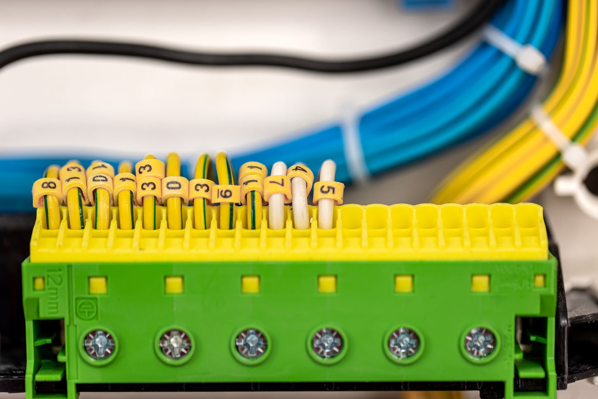
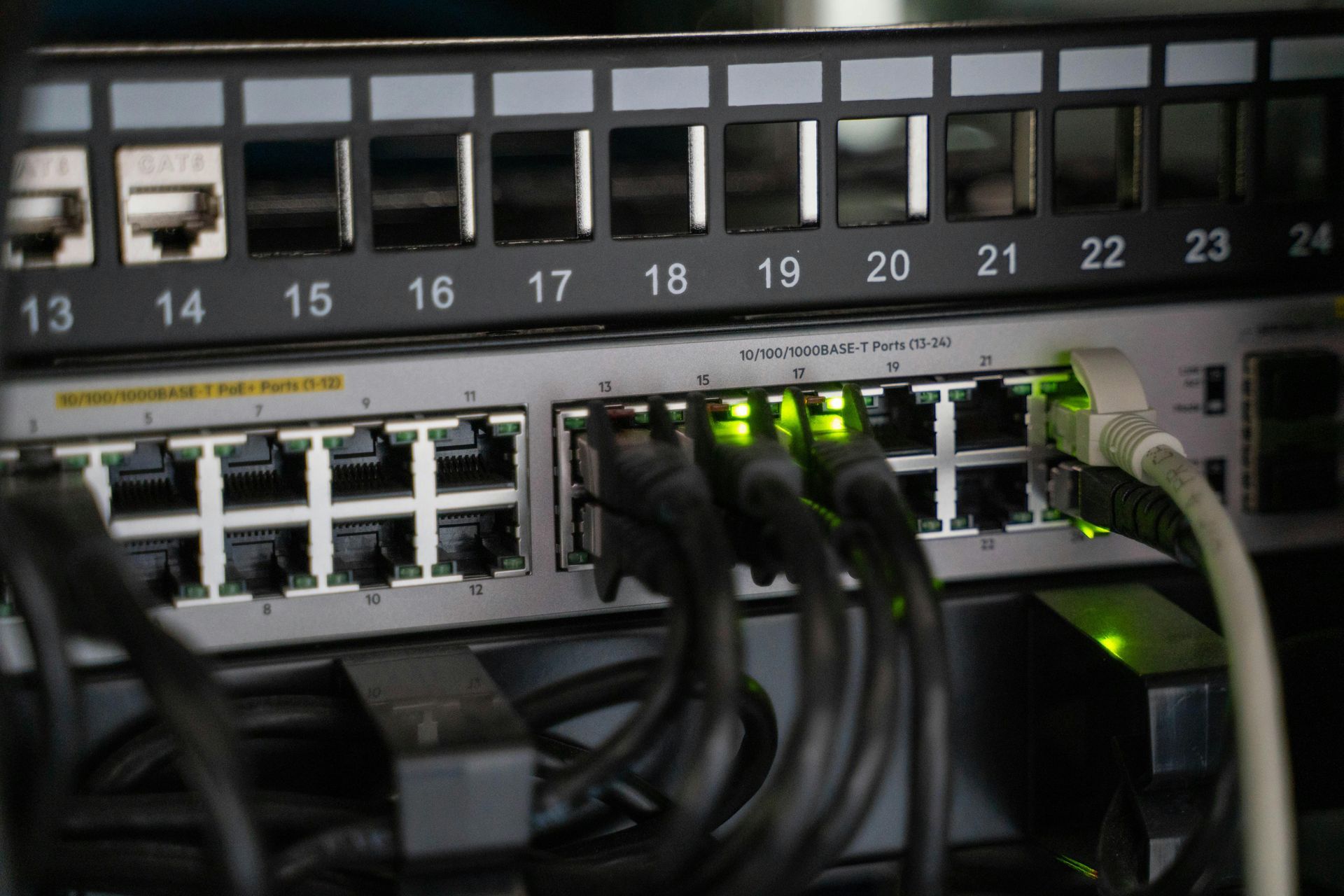
- Connector Discontinuities: In embedded interconnects, poorly designed or manufactured connectors introduce discontinuities that distort the signal.
- Cable Attenuation: Over longer distances, signal strength naturally degrades, especially at high frequencies.
- Crosstalk: Closely spaced conductors can induce noise in neighboring channels, degrading the signal.
- Grounding and Shielding Issues: Inadequate shielding allows EMI to couple into sensitive signal paths.
These issues are magnified in harsh environments where temperature, vibration, and contaminants increase system stress.
Table: Symptoms and Diagnostic Techniques
| Symptom | Possible Cause | Diagnostic Method |
|---|---|---|
| Bit errors or data loss | Reflection, crosstalk | Eye diagram analysis, BER testing |
| Signal distortion | Impedance mismatch | TDR (Time Domain Reflectometry) |
| High EMI emissions | Poor shielding | EMI chamber testing, spectrum analysis |
| Latency or timing errors | Skew, delay variation | Oscilloscope with timing analysis |
| Connector heating | Poor contact integrity | Infrared thermal imaging, resistance measurement |
Tools and Techniques for Identifying SI Failures
Advanced test and simulation tools help engineers detect and isolate signal integrity issues:
- TDR (Time Domain Reflectometry): Measures reflections to locate impedance mismatches.
- VNA (Vector Network Analyzer): Analyzes S-parameters for high-frequency performance.
- Oscilloscopes: Used for eye diagram analysis and measuring rise/fall times.
- Simulation Software: Predicts signal behavior based on layout and material properties.
In real-world environments, these tools must be paired with
robust mechanical and electrical design, especially in defense, aerospace, and industrial systems.
Design Best Practices to Prevent SI Failures
Preventing signal integrity problems starts with good design. Key considerations include:
- Controlled Impedance: Use impedance-matched connectors and controlled-impedance PCB traces.
- Short Return Paths: Minimize loop area for signal and ground to reduce noise coupling.
- Differential Pair Routing: Ensures better noise immunity and balanced signals.
- Proper Termination: Use series or parallel termination to match line impedance.
- Shielded Interconnects:
Select cable assemblies with foil or braid shielding for EMI protection.
Meritec’s design engineering integrates all of these practices, enabling reliable high-speed performance even in rugged applications.
Meritec’s Solutions for Signal Integrity Challenges
Meritec specializes in
high-speed embedded interconnect solutions for demanding environments. Our product portfolio includes:
- Rugged cable assemblies designed for signal integrity across extended temperatures and vibrations.
- Custom impedance matched connectors to reduce reflections.
- Overmolded strain relief assemblies that maintain shielding and prevent cable ingress.
- Hybrid interconnects combining power, signal, and RF with isolated paths.
These systems are extensively tested using signal integrity validation tools including eye diagrams, TDR, and EMI scanning.
Table: Signal Integrity Features in Meritec Interconnect Solutions
| Feature | Benefit |
|---|---|
| Impedance-matched design | Reduces reflection and signal loss |
| Multi layer shielding | Minimizes EMI and crosstalk |
| Overmolding | Enhances durability and ingress protection |
| Precision contacts | Maintains signal continuity under shock/vibration |
| Thermal and vibration testing | Ensures reliability in extreme environments |
Final Thoughts
Signal integrity failures can halt system performance, particularly in high-speed and embedded applications. But with proper diagnosis, advanced tools, and well-engineered interconnects, these issues can be mitigated or eliminated.
Meritec offers proven solutions and design support to help OEMs meet rigorous performance goals across military, aerospace, medical, and industrial sectors.
Contact Meritec today to learn how our signal integrity-optimized interconnects can support your next high-speed embedded system.